10. Topological Quality and Cleaning
Note: The processes described here assume that there is “something wrong” with the original input data and that it needs fixing. More precisely, it is assumed that the input data deviates from the intended geometries significantly enough to warrant some automated adjustment that will (ideally just slightly) modify the measured points, lines and polygons to improve the quality of the outcome. Note also that Survey2GIS assumes that the input data represents geometries on a relatively planar surface, meaning that they are similar to their flat 2D counterparts (i. e. constant Z = 0.0) and have little potential for overlaps and undercuts. If this is not the case or you wish to rather preserve the data closer to those originally surveyed, then set “–tolerance=”, “–snapping=” and “–dangling=” options to “0.0” to reduce the “aggressiveness” of most topological cleaning actions. In addition, option “–topology=” can be used to turn specific cleaning functions on or off (see details below).
GIS-based data processing has specific requirements regarding data quality. One of the most important ones is the topological correctness of data. GIS use topological relations such as “contains”, “intersects” or “overlaps” to query and filter spatial data. In order for such queries to return correct results, the data must be topologically correct.
To improve topological quality, Survey2GIS subjects all selected input data (by default, this means all data, but see 6 for how to reduce the set of geometries to a selection) to some essential checks and tries to automatically fix common problems. It is important to note, however, that the GIS topology model is strictly two-dimensional, and that Survey2GIS is also mostly limited to two-dimensional topology checks and corrections. Basically, what this means is that data is treated as though all Z coordinates were constant “0”. The more planar the actual input data, the better the chances that topological corrections will work accurately and as intended.
Even though many GIS offer their own, sometimes very powerful, topological cleaning tools, it is best to let Survey2GIS do the basic work, as it has the information available at the level of “raw” measurements, whereas the GIS can only work on the reconstructed geometries. There are two stages at which topological errors can be detected: When each input file is being processed and after all geometries found in all input files have been built; and Survey2GIS will report topological issues for both stages separately.
Starting with version 1.5.2, Survey2GIS supports turning on or off specific cleaning operations. Because these operations run consecutively, with some of them depending on the effects of previous ones, there is only group level control. This is achieved via setting option “–topology=” to one of the following values (sections with specific explanations are given in brackets):
none turns off all “drastic” topological cleaning. Some operations are still performed to ensure essential aspects of data quality: duplicate points (9.1.1), splinters (9.1.2), multi-part geometries (9.1.3), self-intersections (9.1.4) and vertex ordering (9.1.9).
basic additionally runs operations that have no or little effect on shape: snapping to shared polygon boundaries (9.1.5), internal polygon boundaries (9.1.6) and intersections (9.1.7).
full additionally runs operations that can have a marked effect on shape, especially of polygons: polygon overlap removal (9.1.5), dangling lines (9.1.8).
9.1 Problems and Corrections
Typical survey data suffers from a limited set of topological error sources and defects, many of which can be corrected automatically by Survey2GIS. This section describes the topological cleaning functions in the same sequence in which Survey2GIS carries them out.
Note that it is unlikely that the results of such automated cleaning will be perfect in practice. Real-world survey data contains erroneous and extreme measurements. In addition, the geometries processed by Survey2GIS are weakly structured (essentially, only by the order of records in the input file/s and the geometry types and sizes), and they have no “natural” hierarchy that would allow for perfect resolution of topological problems in all cases. Therefore, the cleaned output data should always be closely examined and manually improved (e. g. using flexible editing tools in GIS) as necessary.
In some cases, processing line and polygon geometries separately with selection commands (see 6) can provide better control over the cleaning process. It may also be advisable to produce a version of the output with all high-level topological cleaning functions turned off (i. e setting program options “–tolerance=”, “–snapping=” and “–dangling=” to “0”) to be able to review the effects of the cleaning process.
9.1.1 Duplicate Points (Thinning)
Duplicate points result from measurements that are so close to each other that they should actually be considered one and the same point. They often represent redundant vertices and increase the likelihood that hard-to-spot self-intersections in complex polygon boundaries will occur (see 9.1.4). But even simple point measurements can be problematic in this regard, e. g. when duplicate elevation points lead to over-representation during surface interpolation in GIS.
Therefore, Survey2GIS has the option “–tolerance=” that allows to set a distance threshold below which points will be considered duplicates. In such cases, only the first point measurement will be preserved and all of its duplicates discarded. This process is also called “thinning”, and its effect depends on the geometry type:
- Points will be thinned by removing all points that are closer than the threshold to any other point within the same input file.
- Lines will be thinned by removing all vertices whose distance to the next (successive) vertex on the same line is smaller than the threshold.
- Likewise, vertices on polygon boundaries will be thinned by removing all vertices whose distance to the next (successive) vertex on the same polygon boundary is smaller than the threshold.
In the case of 3D data, the distance threshold will be applied to the 3D straight-line distance. This helps preserve intentionally densified measurements along sharp terrain edges.
Point/vertex thinning can be turned off entirely by setting option “–tolerance=” to a value smaller than “0”.
Warning: Large values for the thinning threshold (option “–tolerance=”) can severely degrade the shapes of polygons and lines and produce unintended results. In most cases, using a threshold of a similar magnitude as the (estimated) accuracy of the survey is advisable. If point data must be thinned more aggressively, then the different geometry types can be processed separately using a selection command (see 6).
9.1.2 Splinters
Splinters are geometries that are intended to be lines but have less than two vertices, and geometries intended to be polygons with less than three vertices. Such malformed geometries will simply be discarded.
9.1.3 Multi-part Geometries
While not a “topology issue” in the strict sense, the concept of multi-part geometries is an important aspect of data quality and consistency.
Sometimes physical constraints mean that the geometry that represents a single object must be recorded as separate, spatially disjunct parts. E. g., this may be the case if the area of a polygonal object has been exposed in two separate locations. In order for such multi-part recording to work properly, all parts of the geometry must have the same value in “key_field” and the parser option “key_unique” must be enabled (see descriptions in 4). Provided that this is the case, Survey2GIS will then automatically assemble all parts into one multi-part geometry and assign it only one attribute data record in the GIS output.
9.1.4 Self-intersections of Polygon Boundaries
A self-intersection occurs when a vertex B is placed behind its preceding vertex A in such a way that a straight line from B to its successor vertex C crosses over the existing polygon boundary. Small self-intersections can be hard to spot but will result in triangular, “inverted” areas when visualizing the affected polygon in GIS:
Self-intersections are frequent topological errors that prevent many GIS operations from working properly. Currently, Survey2GIS cannot automatically correct this type of error. However, the risk of self-intersections occurring can be lowered by using a “–tolerance” setting equal to the minimal wanted distance between polygon boundary vertices (see also 9.1.1).
Survey2GIS checks for self-intersections early on, when building lines and polygons from the input data. If this is the case, a warning will be issued. To facilitate manual cleaning of self-intersections, new vertices will be added to geometries at self-intersection points.
Some higher level topological cleaning actions will fail with self-intersections present. In such cases, Survey2GIS will skip further cleaning of the affected geometries and issue a warning. Check the status messages produced at the end of program operation for the total number of detected self-intersections.
9.1.5 Shared Boundaries of Polygons
Note: Automatic cleaning of boundaries of adjacent polygons is a feature that is available starting with version 1.5.2 of Survey2GIS.
Two adjacent polygons share a common boundary along their line of contact. During surveying, however, practical restrictions require that both polygons are recorded completely, effectively recording the shared boundary twice – and most likely with some discrepancies, since it will be impossible to re-record the shared vertices in the exact same locations. Therefore, two fundamental problems will be impossible to avoid:
- Small gaps will be left between polygons, even though they are directly adjacent.
- The boundaries of two adjacent polygons will overlap slightly.
From the point of view of 2D GIS topology, the second case is a topological error if the two polygons are part of the same GIS layer. For the production of topologically correct output data, Survey2GIS will attempt to close unintended small gaps between polygon boundaries, and also to remove overlapping areas of adjacent polygons. For these purposes, it offers two tools that complement each other well:
- Small difference in location between vertices of shared polygons can be compensated by adjusting the affected vertices so that the lie exactly on top of each other.
- Overlapping areas of adjacent polygons will be removed automatically and additional vertices will be inserted, so that the polygons will have identical vertices along their shared boundary.
Only the first tool’s action must be controlled by the user, using the “–snapping” option, which causes a vertex that is part of the outer boundary of polygon B to be moved exactly on top of (“snapped to”) the closest vertex on polygon A (which is assumed to be its “sibling” vertex). The value set for this snapping distance threshold should reflect the locational error margin of attempting to measure the same point location more than once in practice.
The snapping threshold should be chosen to lie well below the typical distance of separate point measurements, but above the accuracy with which an already measured point can be measured again.
The section function for cleaning the boundaries of adjacent polygons is fully automated: If (after snapping), there is still an area of overlap between two adjacent polygons, then the affected area will automatically be removed from the polygon that occurs later in the input data. Additional vertices will be inserted on the shared boundary where necessary:
Best results can be achieved, if:
- Larger (base) objects are surveyed first.
- Smaller, adjacent objects are surveyed later, and a small number of surveyed points are chosen intentionally so that lie a good distance (further than the threshold value for snapping, above!) within the area of the base object.
In practice, the effectiveness of automatic cleaning of shared polygon boundaries will be limited, depending on the complexity of overlaps, and the following should be taken into consideration:
- Relatively small overlap areas have the highest probability of getting fixed automatically.
- The operation is 2D only.
- Polygons with inner boundaries (“holes”: see 9.1.6) cannot be adjusted, if this means that the number of holes would change (otherwise however, polygons with holes will be adjusted correctly).
- When checking for overlap, each part of a multi-part polygon (see 9.1.3) will be treated like an individual polygon, to ensure correct results.
- If the program option “–force-2d” (reduce all output to 2D coordinates) is not provided: Overlap cleaning will commonly create new vertices at boundary intersections for which Z coordinates will be interpolated linearly from neighbouring 3D vertices on the other polygon.
Also note, that the operations described above will likely fail for polygons that have other topological defects, notably self-intersections (see 9.1.4).
9.1.6 Internal Polygon Boundaries (Holes)
The 2D topology model of GIS demands that polygons in one and the same layer may not overlap each other. However, what if polygon B lies completely within the area of/is embedded in larger polygon A? In this case, B must be modelled as an internal boundary (hole) of A. In practice, this can be done in two different ways:
-
The polygon is recorded as a multi-part (at least two parts) geometry (see 9.1.3): First the base polygon and then any number of smaller polygons within its area. The latter will be converted to holes automatically. In order for this to work, the base polygon and every one of its parts must have the same value in “key_field” and the parser option “key_unique” must be turned “on” (see 4).
-
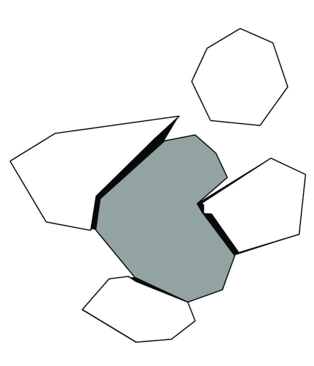
If the embedded polygon is a separate object, then it can be modelled as such by assigning it its own unique key value. In this case, Survey2GIS will automatically “punch” holes into the larger polygon and “fit” all embedded polygons into them without overlap (see illustration above).
In order to get good results from this cleaning process, it is important to record the polygons in a well-defined order (see 12). Also note that the corrections described above are likely to fail when applied to polygons that have topological errors, such as intersecting boundaries (cf. 9.1.7).
9.1.7 Intersections of Lines and Polygon Boundaries
Complex surveys are likely to produce geometries that criss-cross and intersect each other. Such intersection points are often of critical importance for cleaning geometries manually, and intersecting lines are only considered to be topologically valid if they both have a vertex at the exact point of intersection. Intersection vertices also allow for the automated removal of “dangles” (see 9.1.8).
Therefore, Survey2GIS marks intersection points by adding additional vertices to the output data, so that it will be easier to clean the data. There are three cases that lead to additional vertices being added at intersection points:
- Lines crossing other lines (intersection vertices will be added to all crossed/crossing lines).
- Lines crossing polygon boundaries (intersection vertices will only be added to crossing line segments, not to polygon boundaries).
- Polygon boundaries crossing other polygon boundaries (intersection vertices will be added to all crossed/crossing boundaries).
(Note that the last case should rarely occur if boundary vertex snapping is effective: 9.1.5.)
The program will print two different intersection metrics once the data has been processed:
Detected line/polygon boundary intersections: 12
Added vertices at line/polygon boundary intersections: 8
In some cases, the number of intersection vertices added will be lower than the number of detected intersections. This happens, e. g., if a geometry is intersected by more than one other geometry in the exact same location. Such redundant intersection vertices are automatically identified and removed.
Note: Since Survey2GIS cannot know which geometry the user may want to correct manually later, an intersection vertex is added to all intersecting geometries of the same type.
Self-intersections of lines are not considered topological errors by Survey2GIS, but will lead to an intersection vertex being placed on the location of the self-intersection. By contrast, self-intersecting polygon boundaries are topological errors (see also 9.1.4), as are intersections between polygon boundaries (see 9.1.5). If the latter are detected, warnings will be issued and topological errors will be logged, but no intersection vertices will be added.
9.1.8 Dangles (Overshoots and Undershoots)
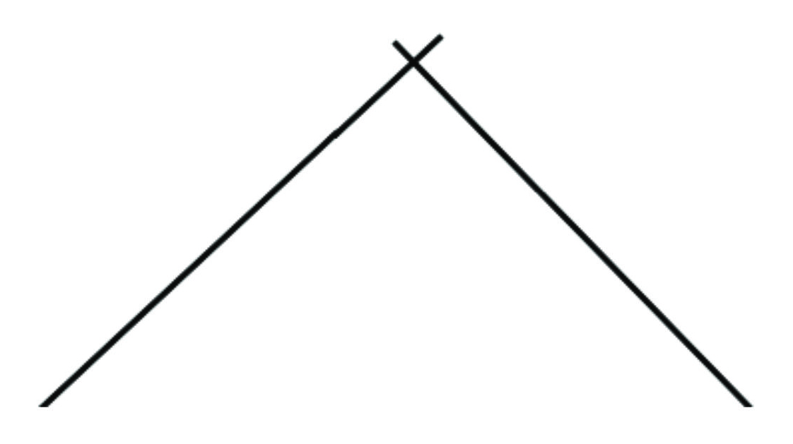
In many cases, the start and end vertices of lines (also referred to as “nodes”) are intended to be located exactly on another line or polygon boundary, but due to the limited accuracy of the survey, they actually lie at a small distance from their intended locations. Such line vertices are collectively called “dangles”, and fall into two categories:
- Line nodes that lie before their intended locations are “undershoots”.
- Line nodes that lie beyond their intended locations are “overshoots”.
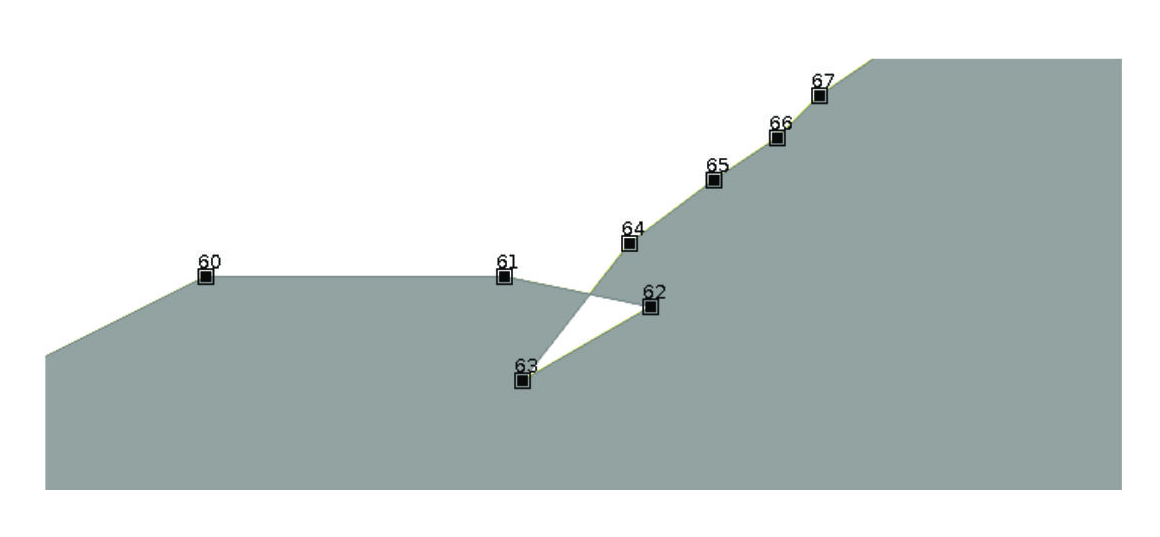
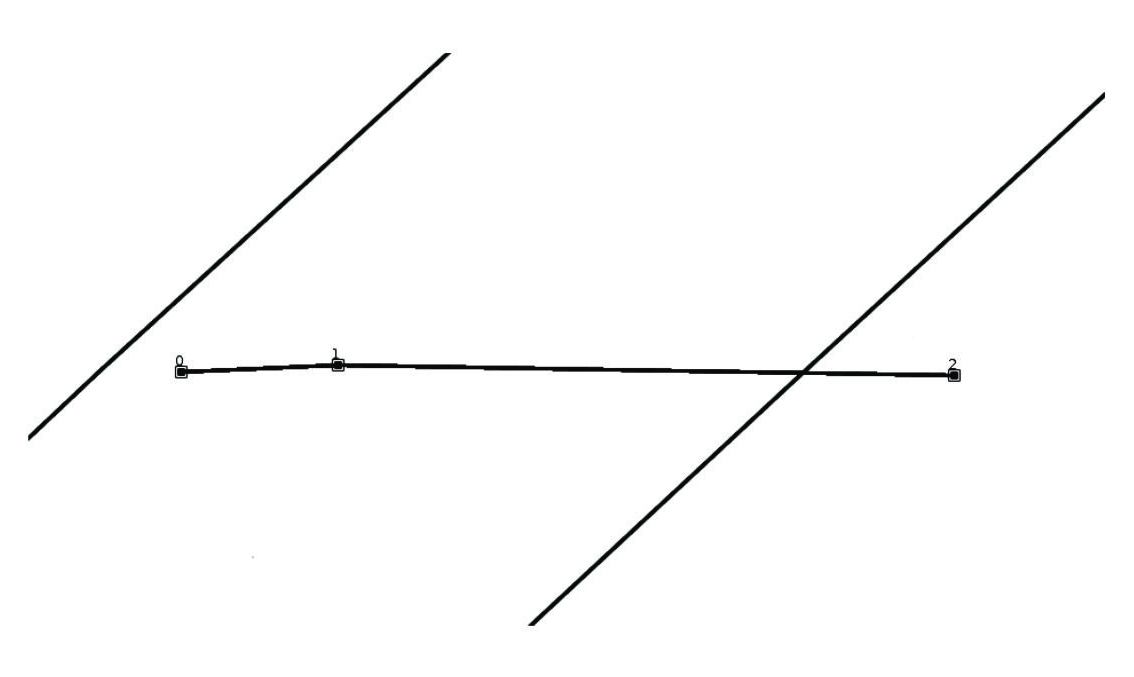
The illustration below shows a line that has both an undershoot (vertex “0”) and an overshoot (vertex “2”).
There is a separate threshold option, “–dangling=”, to control the snapping of dangles to the nearest line/boundary segment. This is needed, because polygon boundary snapping (option “–snapping=”; see 9.1.5) is run first and it can move the vertices of polygon boundaries so much that dangles will no longer snap. Therefore, the dangle snapping threshold should be set larger than the polygon boundary snapping threshold.
Only the first and last segments of a line qualify as dangles, and only if they are succeeded/preceded (respectively) by an intersection vertex (see 9.1.7). If these criteria lead to unsatisfactory cleaning results, and short chains of tiny line segments should also be removed, then consider increasing the “–threshold” option value (see 9.1.1) to reduce such chains to single vertices (note that this may introduce slight inaccuracies into the dangle snapping, as the original line bearing may be modified), or use the intersection vertices added by Survey2GIS (see 9.1.7) to manually remove all excess line segments.
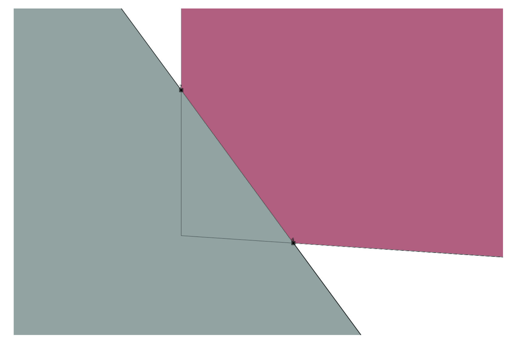
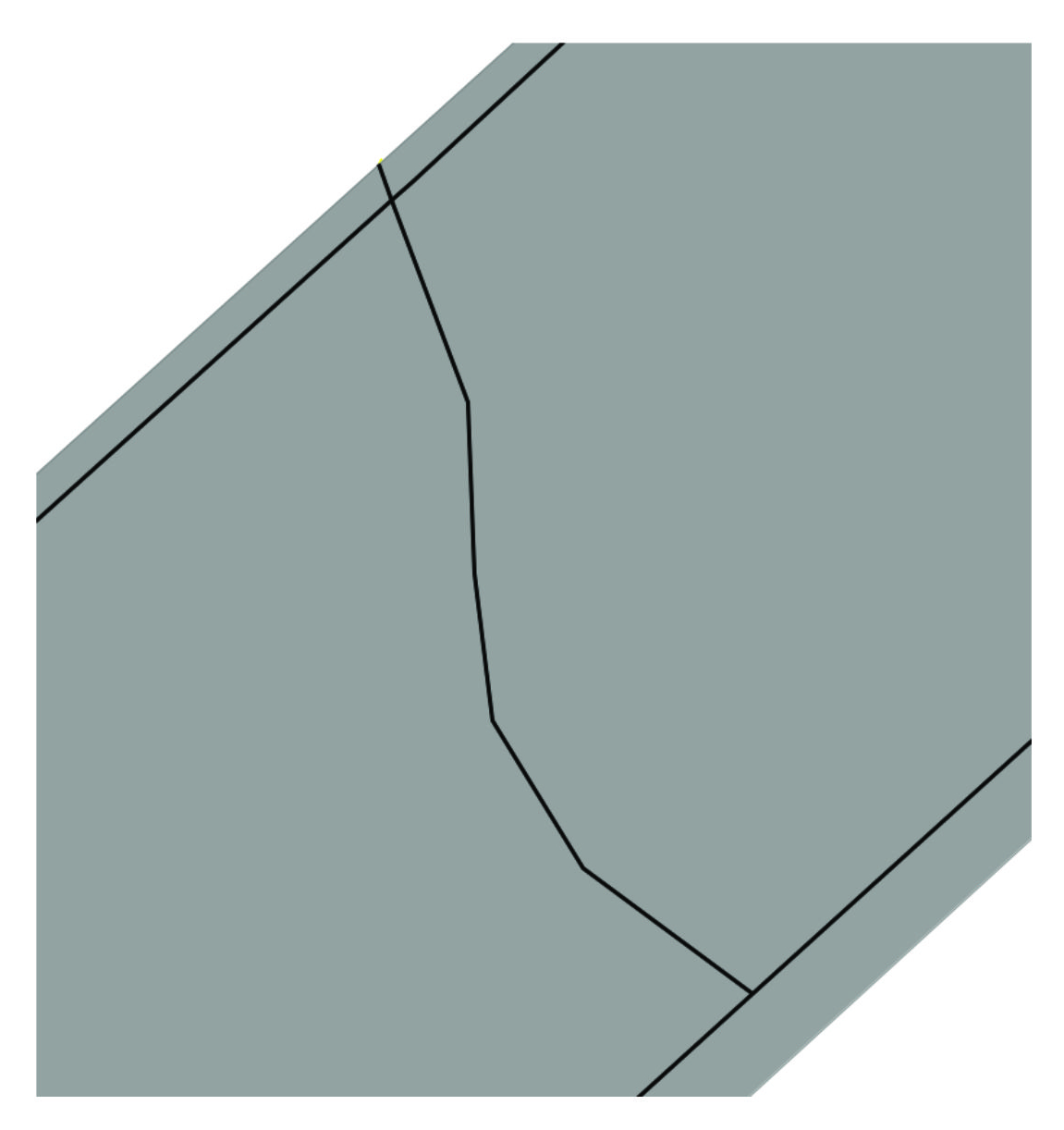
Both overshoot and undershoot corrections will modify original line lengths and both operations can lead to counter-intuitive results if the first or last n vertices are all intersection vertices inserted by Survey2GIS (see 9.1.7). This can happen if e. g. a line segment crosses both another line segment and a polygon boundary segment. In such case, the dangling node will be cut back to the closest intersection point, which may or may not be the ideal/intended snapping position. The image below shows a line that has been snapped to a polygon boundary in the upper part and to a line segment in the lower part during dangle correction:
Sometimes, a dangle might occur to be an overshoot in relation to one geometry and an undershoot in relation to another. In such cases, Survey2GIS picks whichever dangle type is shortest (there is also an extremely small chance that both dangle types will have the exact same length, in which case the dangle will be considered an overshoot by default).
There are some limitations to the performance of automatic dangle cleaning by Survey2GIS:
- Undershoots within the same geometry part (in multi-part geometries: 9.1.3) will not be detected.
- Undershooting dangles are extruded by a 2D distance, so that they snap perfectly to the nearest line segment in a 2D GIS layer. For very long dangles and line segments with a steep Z gradient, this can introduce significant inaccuracies in the Z coordinates of snapped nodes.
- Overshoot correction of short lines that consist of only two segments can also lead to an extreme case where the entire line (part) would be deleted. In such cases, the geometry will not be modified. Instead, a warning message will be issued and a topological error logged.
Therefore, the results of automated dangle cleaning should always be checked carefully and manual corrections applied where necessary (Survey2GIS automatically inserts vertices at crossing points to aid this: see 9.1.7). Use a small threshold for dangle cleaning to avoid overly aggressive modification of line geometries.
A particularly hard problem is posed by “double undershoots” that frequently occur at the corners of line geometries and cannot be detected automatically. Since they do not yield intersection vertices, they are also difficult to fix manually:
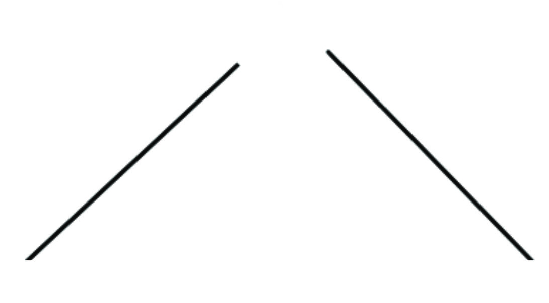
There are two options for avoiding “double undershoots” while surveying:
- Code the geometry as a polygon instead of a line, so that it will be automatically closed.
- Cross the first segment with the last one while surveying, so that an intersection vertex will be generated and the two dangles can be removed as overshoots:
9.1.9 Order of Polygon Vertices
GIS data has a directional component that needs to be considered when digitizing polygonal data. In general, GIS attempt to correct the vertex order (also called “winding order”) of polygons automatically, but it is safer to prevent problems from the ground up.
Visualization of 3D data, in particular, can suffer defects when data with inconsistent vertex ordering is rendered to the screen.
The following rules should be respected when surveying the vertices of polygons (see enumeration of vertices in illustration, below):
- Record the vertices of outer polygon boundaries (also disjunct boundaries of multi-part geometries) in clockwise order.
- Record the vertices of inner polygon boundaries (“holes”) in counter-clockwise order.
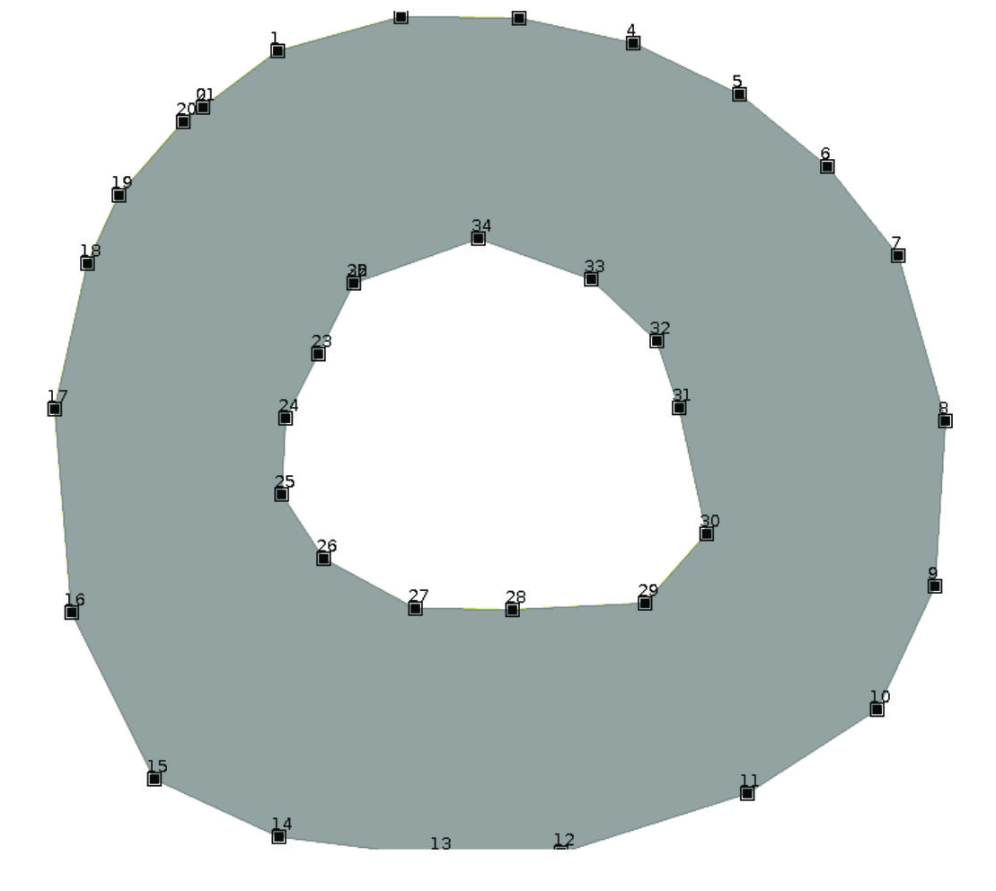
When reconstructing polygons from survey data, Survey2GIS will attempt to enforce the above rules automatically and re-order vertices if necessary. In order to avoid problems, however, it is recommended to respect these rules during field work, when recording polygon outlines.
9.2 Practical Considerations and Limitations
Essentially all common GIS use a 2D topology model based on the concept of a bird’s eye data view. This may cause topological errors to arise, even though the original 3D data is theoretically free of such errors. Polygon boundaries are especially problematic in GIS analysis, because from a 2D top-down perspectives, boundaries may seem to overlap even though they are free of overlap in 3D space. There is no way to automatically correct for such effects.
An alternative is to reduce the 3D input data to 2D data by dropping the definition of the Z coordinate field from the parser schema (4.4). In this case, Survey2GIS will assume all Z coordinates to be uniformly “0” and all topological cleaning operations are reduced to 2D operations.
In any case, complex polygons, at least, should always be inspected carefully and cleaned as needed, using the available GIS tools.
The topological cleaning functions available in Survey2GIS are not suitable for correcting very large or complex topological errors (e. g. multiple overlaps or “holes within holes”). The best prevention of topological errors is rigid self-control and good practice during the survey.
All functions for topological cleaning are run after a reprojection (if any: see 8.2), in order to avoid introducing further inaccuracies into the reprojected result. However, they run before a coordinate transformation to change axes orientations (if any: see 7), so that the result will be unaffected by a change of orientation in the coordinate system.
Topological processing of input data that is provided as latitude and longitude coordinates has severe limitations. Only the following cleaning actions will be performed:
- Removal of redundant vertices (see 9.1.1) and “splinters” (see 9.1.2).
- Check for self-intersections (see 9.1.4).
- Snapping for adjacent polygon boundaries (see 9.1.5).
- Re-ordering of polygon vertices (see 9.1.9).
The removal of redundant vertices and snapping actions use a planar distance measure (to be specified as decimal degrees in this case!), which reduces accuracy. The program will issue a warning message, accordingly.
There are limits to what automated topological cleaning can achieve for complex, real-world survey data, and it may produce unexpected or even erroneous results. This can be avoided by taking these limits into account during field work.
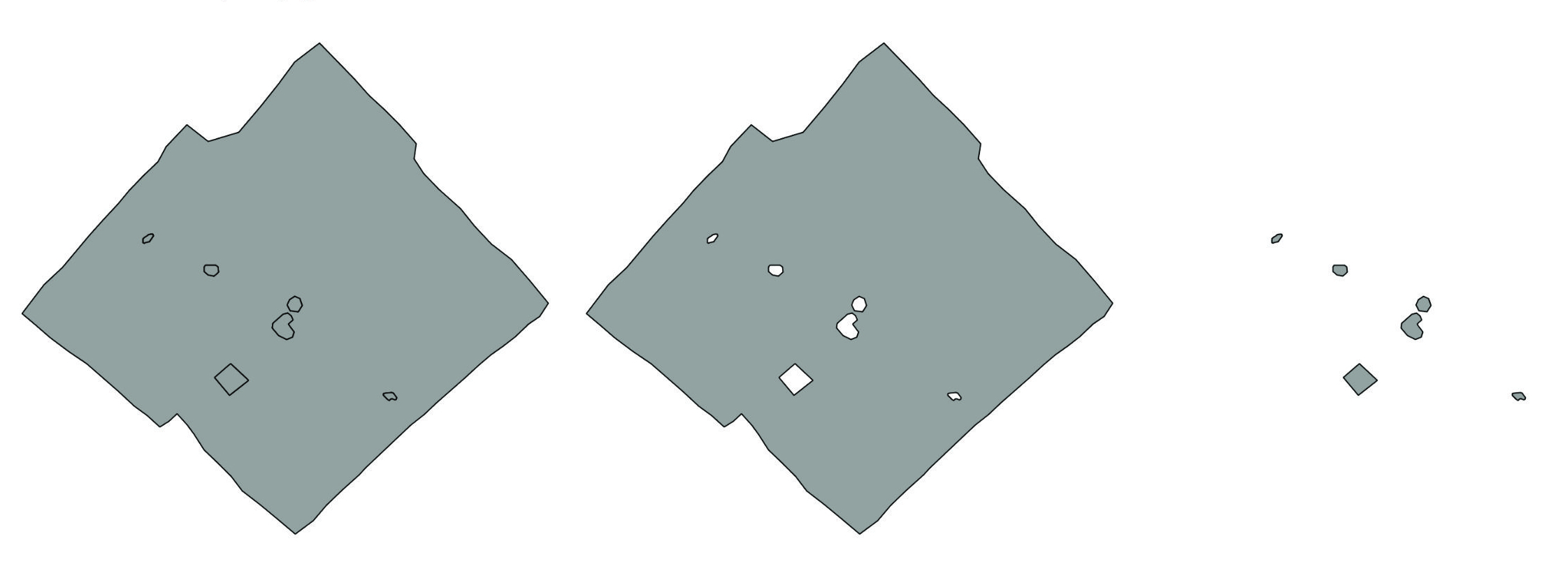
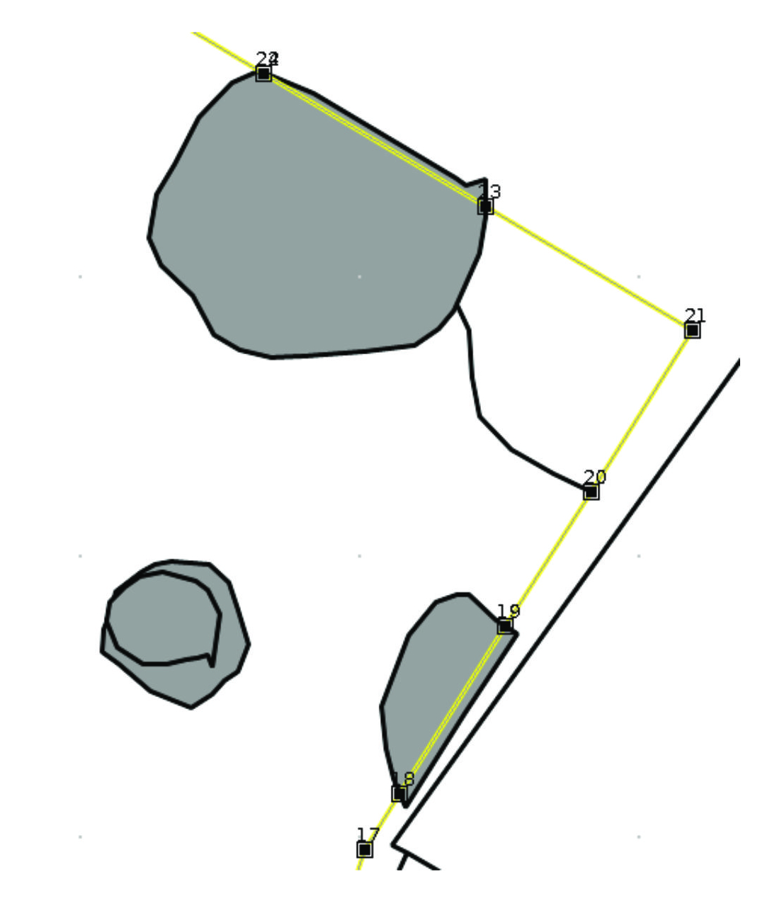
The illustrations below show one of the few extreme cases that will cause the topological cleaning performed by Survey2GIS to fail. In this case an (elongated) polygon completely crosses another (round) polygon. Automated clean will reduce the crossing (elongated) polygon to only its western part. The reason for this is, that the software does not support the splitting of overlapping polygons into multiple parts during cleaning. The solution is to record the overlapped (round) polygon as two separate geometries in the field, surveying only those areas that are actually visible (see also discussion of multi-part geometries in 9.1.3).
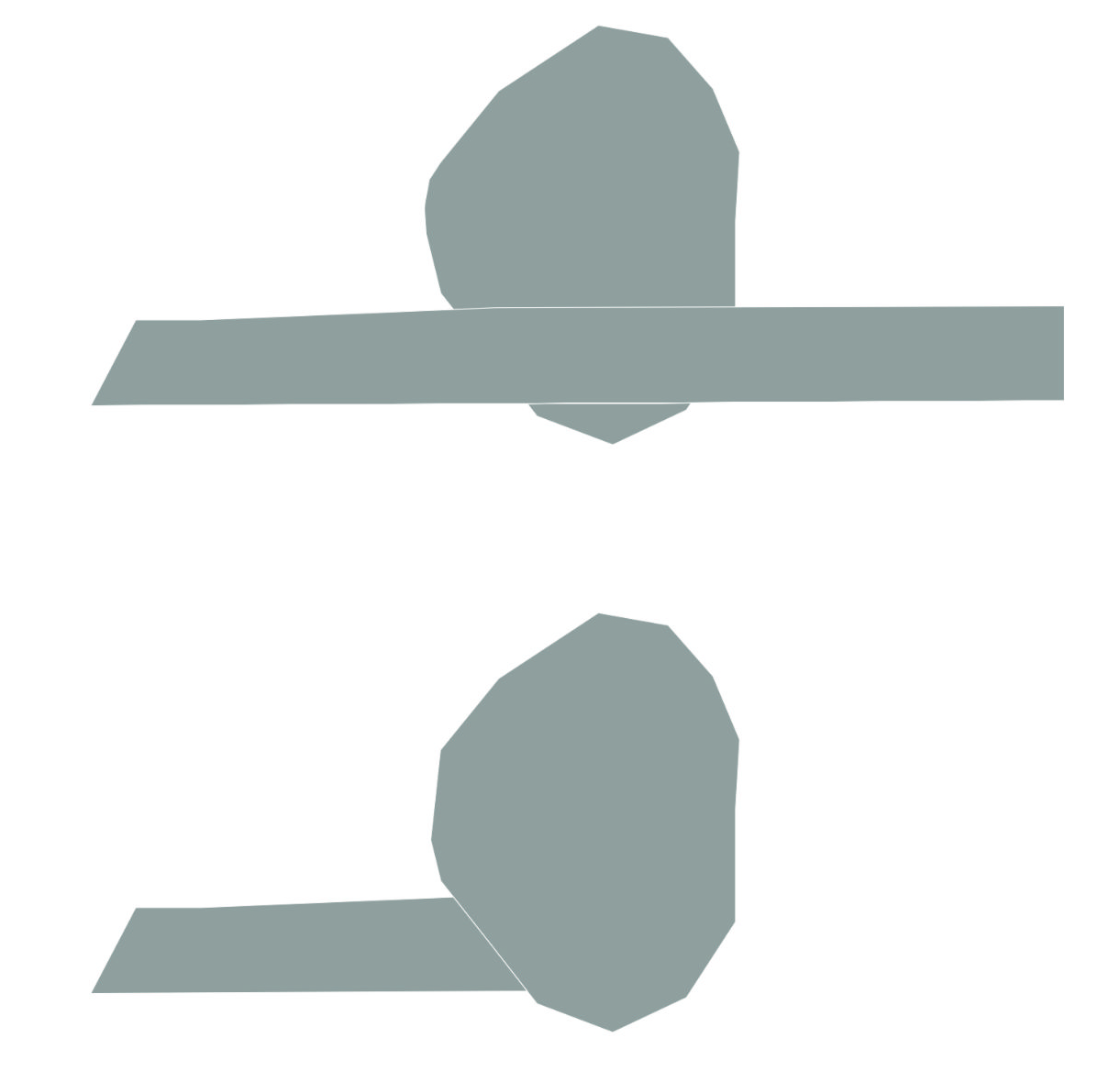
Some tricky cases might require using of option “topology=” to reduce the aggressiveness of automatic cleaning (see 9), and resolving issues manually in GIS.
Important: When combining a data selection (see 6) with topological cleaning, the result can vary from that obtained by processing the complete input data! The reason for this is that geometries not included in the selection no longer have an effect on topological operations in Survey2GIS. For example, polygon boundaries will not be adjusted if the overlap with boundaries of polygons that are part of the data selection. If this behaviour is not desirable, then it might be better to process the data in full and use e. g. a GIS to select data afterwards.